| Home | [an error occurred while processing this directive]History | [an error occurred while processing this directive]RAMBOard 2/C | [an error occurred while processing this directive]1571 RAMBOard | [an error occurred while processing this directive]RAMBOard (std.) |
|---|---|---|---|---|
| [an error occurred while processing this directive] | Speed Control | [an error occurred while processing this directive][an error occurred while processing this directive] | [an error occurred while processing this directive] | References |
The 1571 RAMBOard
Currently there's not much information here regarding the RAMBOard that was built for the Commodore C1571 disk drive. In the process of talking with different people to collect further data for the RAMBOard 2/C, additional items about other revisions of the RAMBOard were collected. One of these items was a scan of the installation manual of the 1571 RAMBOard, which has been converted to ASCII text, retypesetted and put into a PDF file. That way all the content as well as the appearance of the document could be preserved in 100% true electronic form.
-
1571 RAMBOard Installation (PDF-Version, english,
51KB),
converted to eText and recompositioned to match the original as
far as possible.
-
1571 RAMBOard Installation (ASCII-Version, english,
13KB),
eText, as contributed to
Project64,
look it up at the
Commodore
Peripheral Documents section.
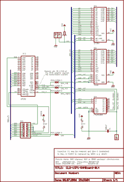
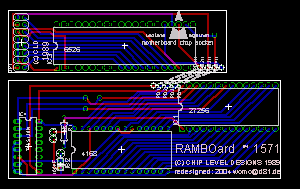
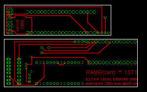
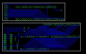
Redesigned board layouts and schematic of CLD's 1571 RAMBOard
In general the 1571-RAMBoard does work the same as explained for the 1541-II RAMBOard, especially as it belongs to make use of so named Pseudo Static RAM, PSRAM.
For the Commodore 1571 floppy disk drive the main difference is that 32kB of ROM are used, therefore the RAMBOard cannot be paged in in the floppy's address space between 0x8000 and 0x9fff. Address room between the addresses 0x6000 and 0x7fff was choosen instead. Because the 6526 CIA used for the fast serial bus and its »Burst routines« along with many mirrored register sets occupies all the address space between 0x4000 and 0x7fff, the 1571 RAMBOard needs to intercept the CIA's /CS chip select signal and regenerate it, so that the CIA gets addressed between 0x4000 and 0x5fff and the RAM extension gets addresses between 0x6000 and 0x7fff.
The 1571 RAMBOard additionally contains two other extended features. When a 27512 EPROM gets inserted and a little switch connected to a jumper pad, the user can easily build a 1571 ROM switch for selecting between two alternative 1571 ROMs. And then a parallel cable connector for the 1571 was added to the 6526 CIA chip socket adaptor. This gives further support to backup software using the parallel burst principle known from »Eurosystems's Burstnibbler«.
| Bill of materials | |||
|---|---|---|---|
| IC1 | - | 27256 EPROM, the drive DOS ROM that has been pulled out of its socket from the drive. This one sits in a precision socket that is sinked into the PCB. | |
| IC2 | - | 4168 pseudo static RAM 8Kx8 (alt. 6264 static RAM) | |
| IC4 | - | MOS6526 CIA, the drive's periphery chip that has been pulled out of its socket from the drive. This one sits in a precision socket that is sinked into the PCB. | |
| IC4 | - | 74LS138 | |
| R1 | - | 1KΩ resistor | |
| C1 | - | 100nF ceramic capacitor | |
| JP1 | - | 2x8 pin header | |
Schematic and board layout for print reproduction
PDF-File of the reengineered version 0.14 of the schematic and layouts of CLD's 1571 RAMBOard


