| Home | [an error occurred while processing this directive]History | [an error occurred while processing this directive]RAMBOard 2/C | [an error occurred while processing this directive]1571 RAMBOard | [an error occurred while processing this directive]RAMBOard (std.) |
|---|---|---|---|---|
| [an error occurred while processing this directive] | Speed Control | [an error occurred while processing this directive][an error occurred while processing this directive] | [an error occurred while processing this directive] | References |
The RAMBOard, standard version for the Commodore 1541
In 2006 there were some newsgroup discussions about CLD's RAMBOard series as well as other CLD hardware and hardware from CLD's competitors. A new call for contributions to this web site, including manual scans and scans or photos of the hardware itself brought in many new artifacts. See the History page for more.
One of these contributions were scans of the installation instructions for the very first item of the RAMBOard series, The RAMBOard for the Commodore 1541 disk drive, as well as the models 1541 A, 1541 A-2 and the former revisions VIC1541 and VIC1540. The »Illustrations« section states that this RAMBOard version is suitable for installation into the Commodore 1541C disk drive model although we know that there is another RAMBOard version specialised for installation into the 1541-II as well as the 1541C.
Leo LaFlamme provided these scans of the installation manuals with digital preservation in mind and this is what this page is dedicated to: Preserving the documentation and other information of well known hardware of the 1980'ties in true digital form. This way support can be given to people who own such hardware items and lost documentation and to people who bought hardware items on flee markets without documentation or other informations on how to install or use them.
-
1541 RAMBOard Installation (PDF-Version, english,
119KB),
converted to eText and recompositioned to match the original as
far as possible.
-
1541 RAMBOard Installation (ASCII-Version, english,
14KB),
eText, as contributed to
Project64,
look it up at the
Commodore
Peripheral Documents section.
ATTENTION: On the illustrations page, the picture for the 7 inches mainboard was drawn incorrectly. From Commodore service manuals and several pictures of the Commodore 1541C disk drive model it is known that the processor 6502 sits inbetween the both 6522 VIA chips. The documents above contain some corrections with this issue. Further the illustration picture does not show the 40 pin floppy controller gate array IC.
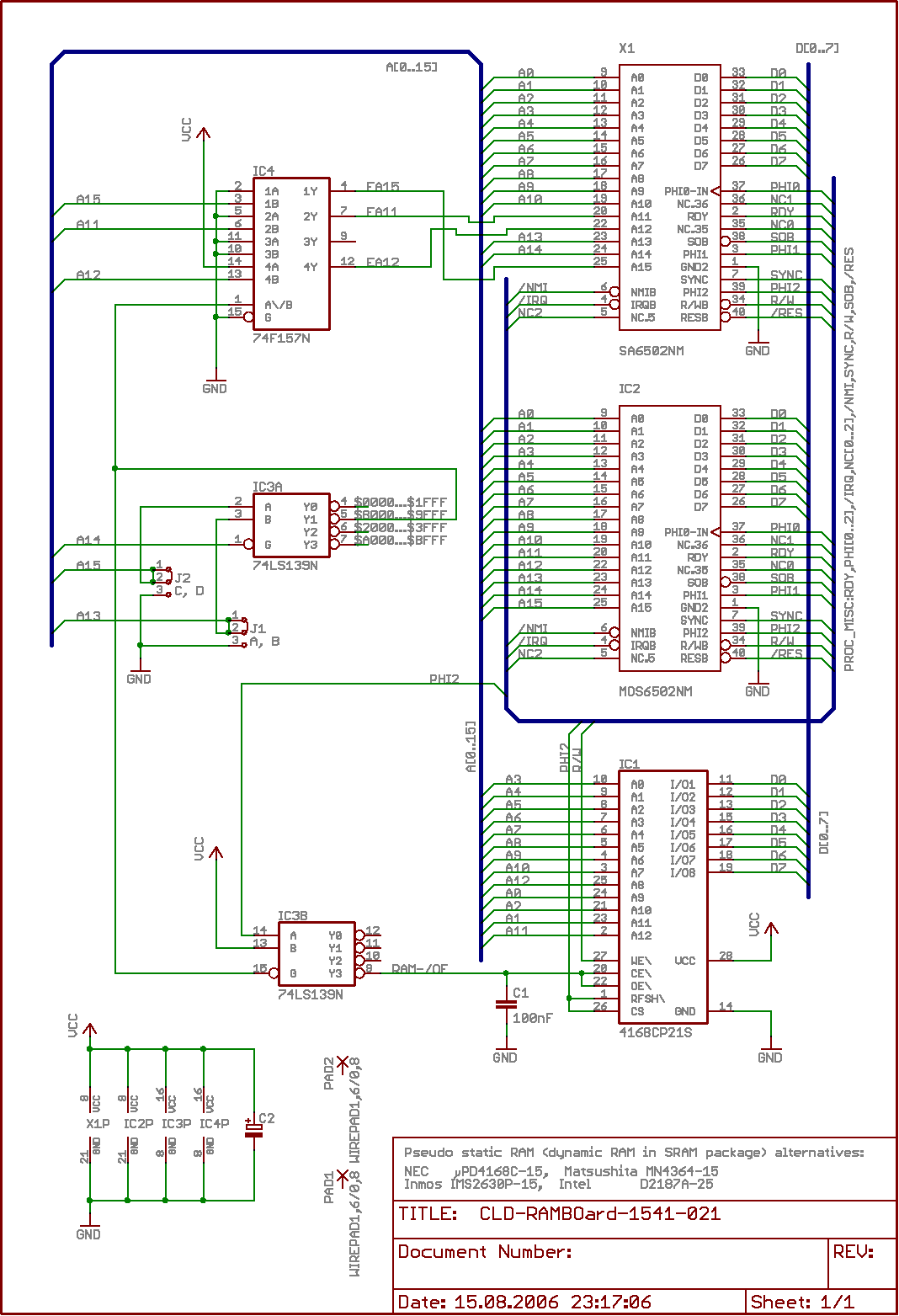
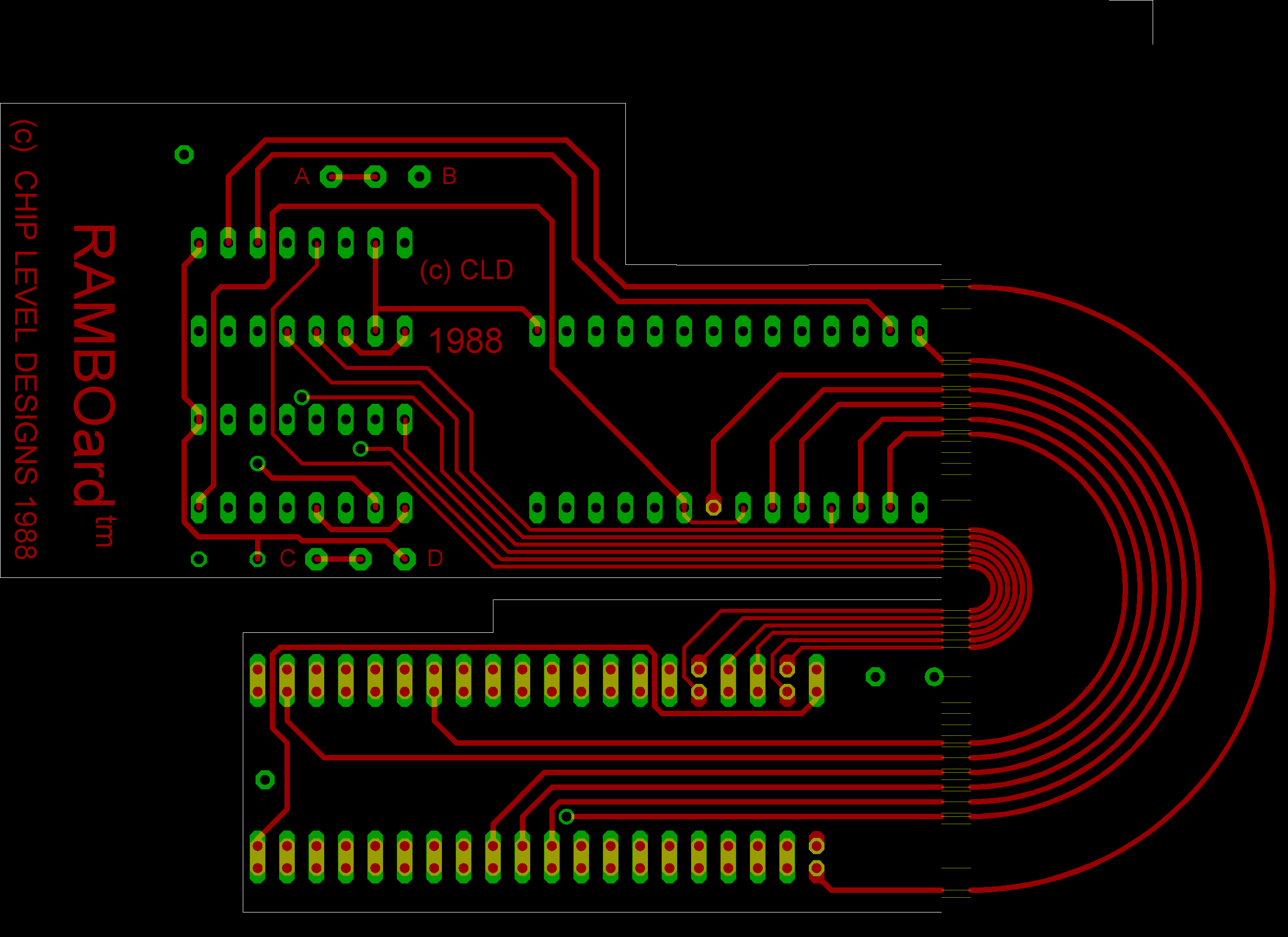
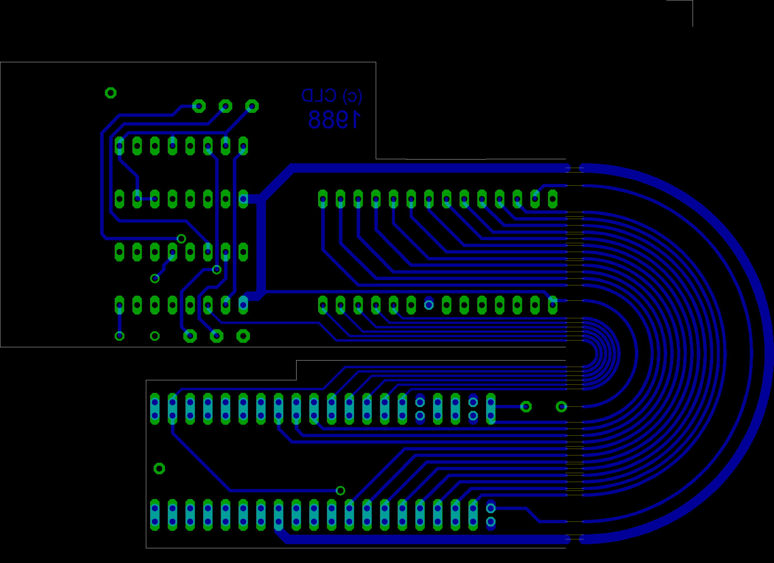
Redesigned board layouts and schematic of The RAMBOard

Again the 1541 RAMBOard does work the same as the other RAMBOard versions. The main difference is that this RAMBOard version intercepts (is connected to and replaces) the 6502 processor while the other version intercept the DOS ROM.
This RAMBOard locates to address 0x8000 up to 0x9fff. Because the 6502 processor is intercepted directly, a fake address needs to be given out to the mainboard's address bus, whenever the internal RAM is selected. Therefore the RAMBOard circuitry not only needs a chip for address decoding (74LS139 or 74SC139), but another one, a 74F157 (or 74LS157), for generating the fake address.
The settings of the preselected jumpers »A/B« and »C/D« are somewhat unclear. Most probably, with jumper »A/B«, the RAMBOard can be disabled, if the default trace towards »A« gets opened and a switch connected. Position »A« then means RAMBOard enabled, position »B« means that the RAMBOard is disabled. Jumper »C/D« does not make much sense in addition to »A/B«, also it could be used as a disable switch like »A/B«.
The board layout is shown somewhat crippled over here. The freeware version of CadSoft Eagle does not allow to create boards of the size of the RAMBOard presented here. Therefore this »folded« design was selected. You perhaps may want to recombine the both halfs with a photo manipulation software.


| Bill of materials | |||
|---|---|---|---|
| X1 | - | 40pol. precision socket adaptor, connects to the 1541 drive processor socket, the one where the 6502 processor was pulled out. | |
| IC1 | - | 4168 pseudo static RAM 8Kx8 (alt. 6264 static RAM) | |
| IC2 | - | 6502 processor, the one that has been pulled out of its socket from the drive and plugged into a socket provided by the RAMBOard. | |
| IC3 | - | 74LS139 | |
| IC4 | - | 74LS157 | |
| C1 | - | 100nF ceramic capacitor | |
| C2 | - | 10µF electrolytic capacitor, most probably omitted on all manufactured devices | |
Schematic and board layout for print reproduction
PDF-File of the reengineered version 0.21 of the schematic and layouts of The RAMBOard