| Home | [an error occurred while processing this directive]The Hardware | [an error occurred while processing this directive]Versions | [an error occurred while processing this directive]Documents | [an error occurred while processing this directive]Protected Area |
|---|
|
|||||||
|
|||||||
Documentations about a sample of the Floppy-Speeder version: Professional-DOS Release
The table below contains some scan pictures of a Professional-DOS Release PCB, the ROM and tools disk, that was provided with it. There are also some descriptions (mainly PDF files) about the hardware listed, see the Hardware⇒Electronics-section of the Professional-DOS Version 1 for further explanations for these descriptions.
It's interesting to see, that some of the part numbers of the little TTL-ICs can be read. One is not polished and can be identified as a 74LS00. Another one isn't polished completely and can be identified as 74LS173 (not really simple).
| A C1541 drive expansion board of Professional-DOS Release | Web picture, 150 dpi | Download, 1200 dpi |
|---|---|---|
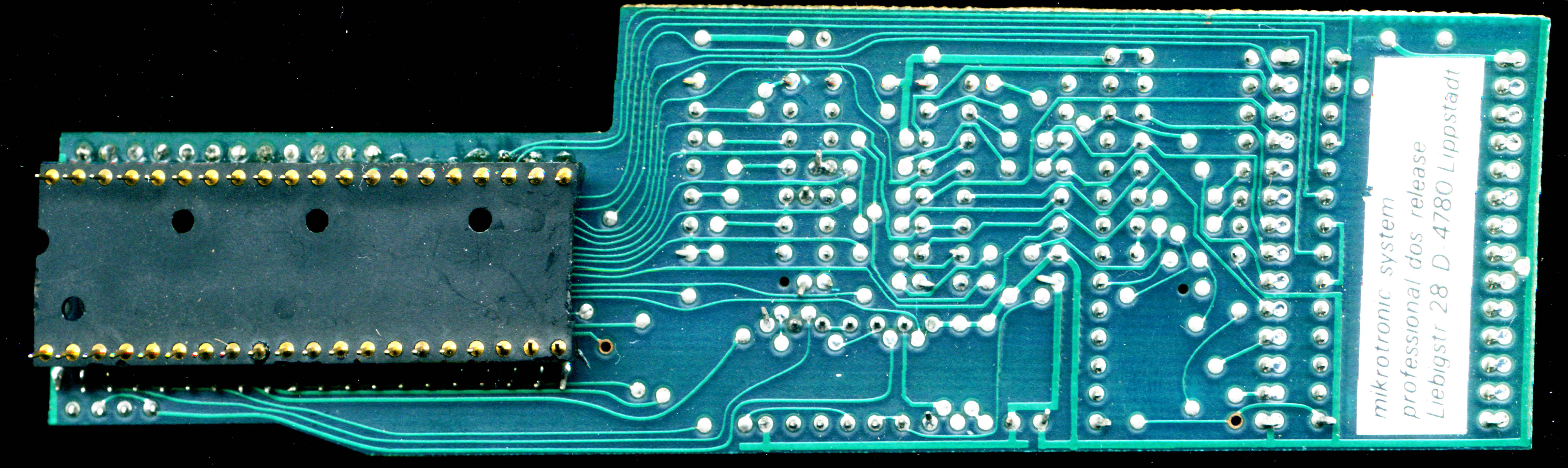
| Drive PCB viewed from the solder side |  837x250, 837x250,99 kB | 6700x2000, 714 kB |
| Drive PCB viewed from the parts side | 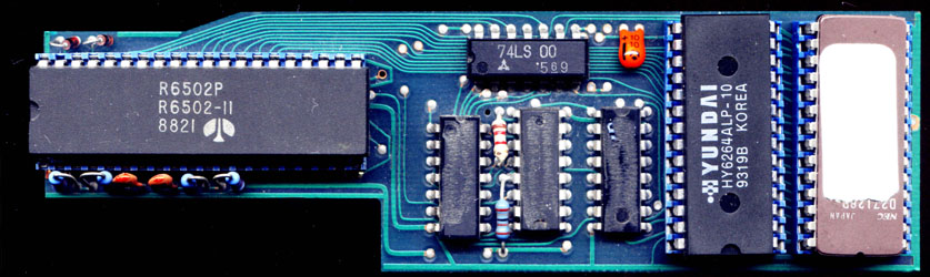 837x250, 837x250,89 kB | 6700x2000, 690 kB |
| Drive PCB viewed from the parts side with some parts removed | 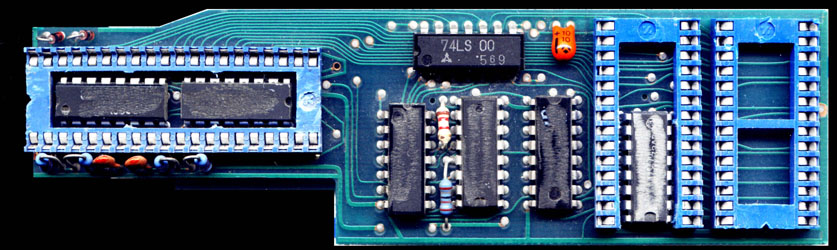 837x250, 837x250,104 kB | 6700x2000, 737 kB |
| ROM set and tools | Headerless binary format (PC based) | Commodore format (with load address) |
| ROM set (floppy ROM dated to: 19.01.1987) and tool disk | ROM set (23KB) | Kernals and tools disk (32KB) |
| Hardware description | PDF format | Alternative version |
| Crossconnection table of the Release variant PCB | Rev.: 2002-10-06 (11KB) | n.a. |
| Schematic of the Release variant | Rev.: 2003-05-25 (281KB) | Eagle format (ZIP, 54KB) |
| PROM content (address decoder) descriptions | Decoder description (14 KB) | PROM dump (Text, 2 KB) |
Some ROM internals
The C64 kernal ROM version of this variant seems to be widely held, because it can be found on other web pages. Maybe because this version was the most used one (C64, C1541, userport connection).
Having a look into the disassembly of the drive ROM (partly), we can see similar routines as showed in Hardware⇒ROMs. The most important changes, that may come to your eyes is a change in the addressing from Professional-DOS Version 1 to the Release variant showed here. Not only the ROM location of the DOS expansion ROM changed from 0x9xxx to 0x6xxx, but the GCR tables also from 0x8xxx to 0x7xxx. Additionally the half nibble tables aren't grouped by 256 bytes anymore (0x80xx/0x81xx) but by 2048 bytes (0x70xx/0x78xx).
...
6045 50 fe bvc $6045
6047 b8 clv
6048 ae 01 1c ldx $1c01
604b bd 00 78 lda $7800,x ; preload internal nibble register
604e bd 00 70 lda $7000,x ; decode 1st nibble
6051 50 fe bvc $6051
6053 b8 clv
6054 ae 01 1c ldx $1c01
6057 1d 00 79 ora $7900,x ; decode 2nd nibble
605a c5 39 cmp $39
605c d0 73 bne $60d1
605e bd 00 72 lda $7200,x ; decode 3rd nibble
6061 50 fe bvc $6061
6063 b8 clv
6064 ae 01 1c ldx $1c01
6067 1d 00 7b ora $7b00,x ; decode 4th nibble
606a 85 1a sta $1a
606c bd 00 70 lda $7000,x ; preload internal nibble register
606f 50 fe bvc $606f
6071 b8 clv
6072 ae 01 1c ldx $1c01
6075 bd 00 78 lda $7800,x ; decode 5th nibble
6078 1d 00 71 ora $7100,x ; decode 6th nibble
607b 85 19 sta $19
607d 45 1a eor $1a
607f 85 1a sta $1a
6081 50 fe bvc $6081
6083 b8 clv
6084 ae 01 1c ldx $1c01
6087 bd 00 7a lda $7a00,x ; decode 7th nibble
608a 1d 00 73 ora $7300,x ; decode 8th nibble
608d 85 18 sta $18
608f 45 1a eor $1a
6091 85 1a sta $1a
6093 50 fe bvc $6093 ; decode next 5-byte GCR group
6095 b8 clv
6096 ae 01 1c ldx $1c01
6099 bd 00 78 lda $7800,x ; preload internal nibble register
609c bd 00 70 lda $7000,x ; decode 1st nibble
609f 50 fe bvc $609f
60a1 b8 clv
60a2 ae 01 1c ldx $1c01
...
...
Hardware differences (floppy expansion PCB)
The addressing changes are caused by some changes in the hardware of the drive expansion PCB and the address decoder which is built with a simple 32 byte PROM.
In comparison to the schematic explained in Hardware⇒Electronics, the main difference is, that address line A11 is now used for simulating unused external addresses; instead of address line A13. This requires the address line A11 as input to the PROM address decoder instead of A8 and causes the ROM code changes showed above. A change independent from the A11 address line change is, that the Flip-Flops are now set by writing different addresses in the address range from 0x6800 to 0x6fff.
Another change is, that the ROM chip select signal (/CE) is now switched together with the ouput enable signal (/OE). It seems, that the GND connection between pins 1 and 21 of the 6502 processor was cut on the PCB of this revision. Maybe because of a complicated layout of the PCB.
Summarized, the RAM/ROM mapping of the release variants of Professional-DOS is as following:
- RAM location: 0x4000...0x5fff
- DOS extension ROM: 0x6000...0x6fff
- GCR tables: 0x7000...0x7fff
- DOS replacement: 0xe000...0xffff (original ROM socket remains empty)